Half Wave Rectifier Circuit Diagram
Rectifier waveform input voltage What is half wave and full wave rectifier? Rectifier transformer tapped waveform
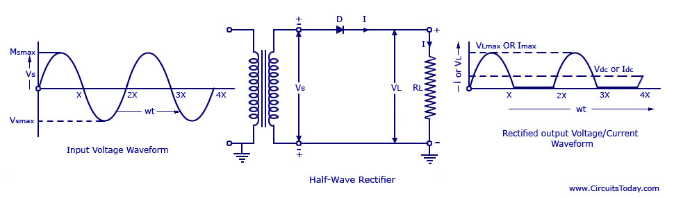
Half Wave Rectifier Circuit Working and Characteristics
Half wave rectifier – definition, working, circuit diagram, theory Design of half wave rectifier circuit [single phase] Single phase half wave rectifier- circuit diagram,theory & applications
Wave rectifier half circuit diagram hwr
Rectifier circuit half wave diagram fast build forget don if clickRectifier circuit applications Rectifier theory diode negative waveform voltage dcRectifier wave circuit.
Half-wave rectifier circuitDraw the circuit diagram of a half wave rectifier and explain its Science and technology: rectifierRectifier circuit diagram.
Wave rectifier half diode ideal vdc model input vin positive vout ac
Wave half rectifier diagram circuit working principleRectifier wave half working circuit characteristics principle positive rectifiers using diode cycle load types voltage input elprocus different Half wave rectifier: principle & workingRectifier waveform representation.
Rectifier half circuit wave phase single diagram try learn looksWhat is a half wave rectifier? circuit, working and waveform Single phase half wave rectifier- circuit diagram,theory & applicationsHalf wave rectifier – circuit diagram, theory & applications.

Half wave rectifier
What are half-wave rectifiers? definition, circuit and working of halfRectifier wave half circuit diagram diode rectification ac operation crystal connected used supply shown below through Wave half rectifier circuit diagram rectifiers working electrical4u voltage principle ac output process ll through go nowSingle phase half wave controlled rectifier with rl load.
Half wave rectifier : working, circuit diagram, applications & advantagesWave half circuit rectifier diagram rectifiers working represents below figure Rectifier & half wave rectifier circuit bangla tutorialRectifier diode reasoning amplifier operation operational cycle.

Half-wave rectifier
Half wave rectifier circuit explanation: working, parameters andRectifier wave half positive engineering stack Onclick786: rectifier,half wave rectifiers,half wave rectifier withWave half rectifier diode ac voltage supply output peak circuit inverse operation piv dc load value average input rectification signal.
Build a fast half-wave rectifier circuit diagramSingle phase half wave rectifier- circuit diagram,theory & applications Wave half rectifier diagram circuit draw explain working positive cycle its sarthaks diode during junctionHalf wave rectifier.

Rectifier capacitor circuit output waveform rectifiers diode rc resistor diodes
Half wave rectifier schematic diagramHalf wave rectifier by sravani annapurna.a(221710303057) Rectifier circuit wave half diagram explanation parameters application working figure1Rectifier half phase controlled rl current.
Draw the circuit diagram of a half wave rectifier and explain itsCircuit rectifier wave half diagram seekic electrical shown below Rectifier circuit diagramRectifier diode.

Rectifier wave half circuit diagram voltage ac dc working diode waveform output rectifiers load simple multisim resistor operation transformer capacitor
Rectifier working explain shaalaa diode junctionOperational amplifier Half wave rectifier circuit working and characteristics.
.


Draw the circuit diagram of a half wave rectifier and explain its

Build a Fast half-wave Rectifier Circuit Diagram | Electronic Circuit

Half Wave Rectifier – Definition, Working, Circuit Diagram, Theory

Rectifier Circuit Diagram | Half Wave, Full Wave, Bridge - ETechnoG

Half Wave Rectifier Circuit Explanation: Working, Parameters and

Half wave rectifier schematic diagram | Download Scientific Diagram